
Building the next-generation space antenna

Team from University of Waterloo designs innovative antenna technology for M3MSat (Maritime Monitoring and Messaging Microsatellite)
Thanks to the cooperation of experts from government, industry and academia, M3MSat carries a cutting-edge Automatic Identification System (AIS) antenna to be tested in space. The result? A one-of-a-kind antenna (both physically and functionally) that promises to improve Canada's capability to monitor and manage marine traffic from space.
This is the story of how this small but powerful antenna was developed and how space projects push us to innovate!
The research and design team
The antenna was designed by a large academic team from the University of Waterloo's Centre for Intelligent Antenna and Radio Systems (CIARS) in close collaboration with industrial experts from COM DEV International (now Honeywell Canada) and space qualification testing specialists at the Canadian Space Agency's (CSA's) David Florida Laboratory (DFL). CIARS has some 35 to 40 active researchers, including 18 to 20 post-graduate students. Many of them were involved in this research. The core research team was made up of a principal investigator, a lead researcher and two PhD students.
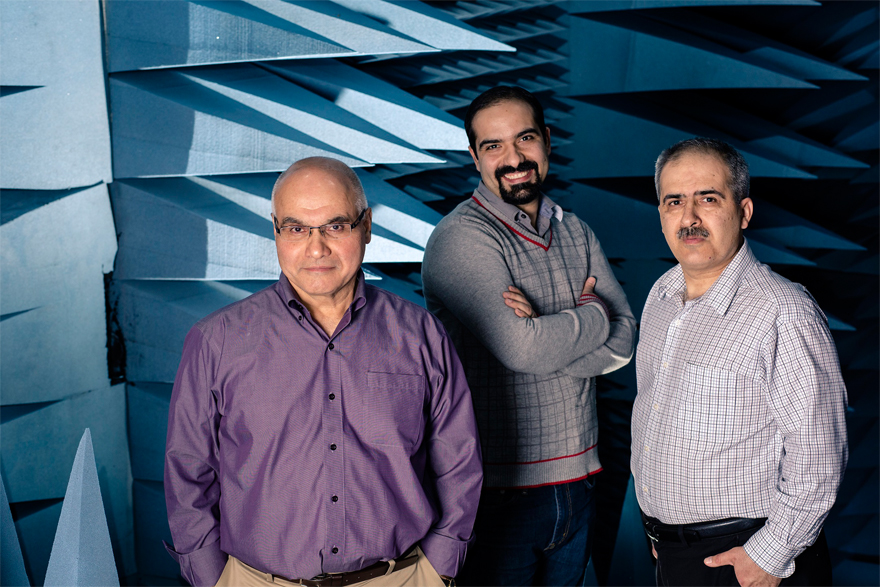
University of Waterloo's core research team - Left: Professor Safieddin (Ali) Safavi-Naeini – Director, CIARS and Principal Investigator. (Centre: Dr. Aidin Taeb (PhD candidate during the project), Feed structure design and simulation. Right: Dr. Reza Rafi (Assistant Director of CIARS), Lead researcher in the computational simulation and design optimization of the antenna system. Absent: Dr. Mehrbod Mohajer (PhD candidate during the project), Simulation and design of the antenna.) (Credit: University of Waterloo)
Unique challenges call for unconventional solutions
Antenna design begins with a clear understanding of the specific situation, requirements and constraints. For this particular project, a number of challenges made the design very complex.
The team had to address the issues presented by
- keeping the antenna size small while maintaining a high level of performance;
- measuring the efficiency of the antenna on the ground; and
- coming up with a design that can sustain the space environment.
Diagram – Wavelength and wave motion
Credit: Leisure and Cultural Services Department, Hong Kong, China
Did you know?
- The size of satellite antennas are related to the reception and transmission of wavelengths.
- There is a inverse relationship between frequency and wavelength.
- Low Frequency = Long Wavelength/red line in the diagram = Large Antenna
- High Frequency = Short Wavelength/blue line in the diagram = Small Antenna
1. Conflicting Design Requirements: Small is smart!
The task
Develop an antenna design that:
- Fits on a microsat platform
- Does not require deployment
- Receives signals as efficiently as a large antenna
The design
Development of a unique design made of four spiral slots backed by a shallow metallic cavity:
- Offering high radiation efficiency for high performance
- Less negative interaction with neighbouring antennas and the satellite structure
- Curved shape allows a large antenna to be squeezed into a small space
The result: Eureka!
A compact antenna that can receive ship AIS signals from all directions and in a redundant fashion such that even if half the antenna fails, it will still receive all the AIS signals albeit with a weaker signal strength. As opposed to current simple AIS antennas (think of straight antennas on cars), the M3MSat AIS spiral antenna has also been specifically optimized for horizon-to-horizon coverage without any holes that could prevent some AIS signals from being received.
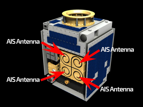
Credit: Canadian Space Agency
2. Antenna measurement challenges: On the same wavelength!
The team encountered two key challenges when measuring and testing the antenna. First, because the actual body of the satellite has an impact on the antenna pattern and performance, the whole system had to be tested together (i.e. with the antenna on the satellite). Second, since the AIS frequency is relatively low, it results in a long wavelength that requires a very large anechoic chamber to verify the antenna performance. Although CIARS and COM DEV Ltd. both have antenna testing facilities, the team needed a bigger one.
Ultimately, the antenna was tested using a mock-up of the satellite at the CSA's DFL, located in Ottawa. The DFL's largest anechoic chamber made it possible to measure the antenna on the replica of the satellite.

Testing of M3MSat in the anechoic chamber at the DFL in Ottawa. The room is designed to completely absorb reflections of electromagnetic waves. It is important to test the antenna in a "signal-free" location to avoid interference or false results and simulate the open space environment. The shape of the blue cones is adapted to trap and absorb electromagnetic waves spanning a broad range of frequencies. (Credit: Defence Research and Development Canada)
3. Unique requirements for space antennas: Shake it up!
When building a satellite or any hardware that will operate in space, there are unique challenges to consider: the hostile space environment and the extreme vibrations experienced during launch. To minimize these risks, all space components are subject to a series of space qualification testing.
In this case, the "space" requirement imposed serious constraints on the overall design of the antenna. Structural qualification tests (particularly those related to shock resistance) prevented the team from using some of the most common interconnection techniques and circuit structures. This aspect of the project made the design much more complex and led to a few design modifications along the way. In fact, two engineering model designs did not pass the space qualification tests. But in the end, the final design made it through and was declared space qualified.

Testing of M3MSat at the DFL in Ottawa. The satellite is placed on a shaker that simulates the vibrations experienced during launch. A series of these tests are conducted by COM DEV's mechanical engineer Dwight Caldwell and the M3MSat team. (Credit: Defence Research and Development Canada)
Learning through collaboration and innovation
The challenges of this mission brought together the unique strengths of the different players. Government provided the vision and identified the requirements for the project; a strong science and research component was steered by academia; and industry provided leadership in managing the complex and subtle expertise required to deliver M3MSat.
According to Professor Safieddin (Ali) Safavi-Naeini, the Principal Investigator and Director of CIARS, the AIS antenna for M3MSat was one of the most challenging antennas ever designed and developed by CIARS, but it was also "…one of the most interesting antenna design projects we have worked on; we learned so much from the experience." Under his leadership, the centre is pursuing other space-related projects, including aircraft-to-satellite and car-to-satellite communications.

An image depicting satellite antennas receiving AIS signals emitted by vessels, which are stored onboard the satellite, and retransmitted when in view of an appropriate ground station. (Credit: European Space Agency)
For more information:
- Maritime Monitoring and Messaging Microsatellite (M3MSat)
- Centre for Intelligent Antenna and Radio Systems
- COM DEV Missions group
- Date modified: